As far back as I can remember, I’ve always wanted to see inside an autofocus lens to see how it worked.
As I was cleaning out a closet the other day, I found some old Minolta MAXXUM lenses. One of them was the 50mm f/1.7 pictured below. I hopped on eBay and found a few “like new in box” editions were going for about $35. Since it wasn’t worth it to try and sell it, I grabbed my toolkit and my digital camera and documented the dissection.

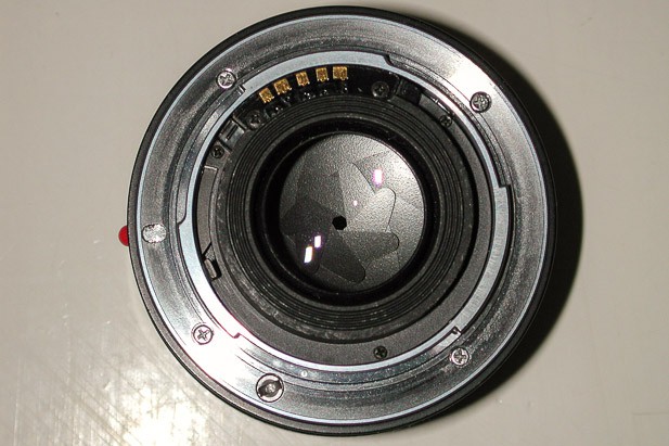
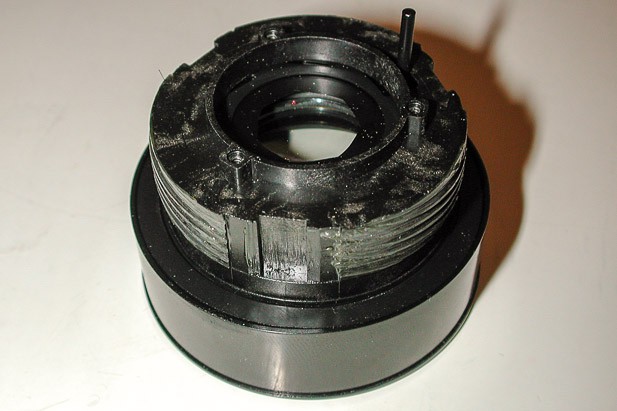
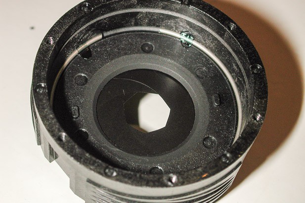
The computer chip in the upper left tells the camera what kind of lens is attached as well as the minimum and maximum aperture of the lens. The big hole on the right side at about three o’clock is where the autofocus coupler sits.
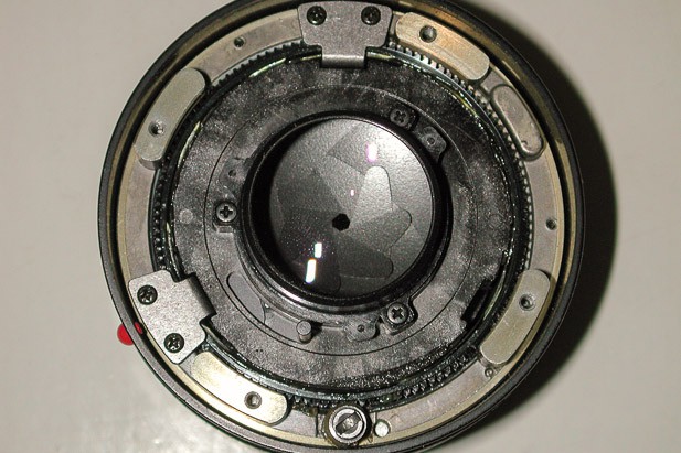
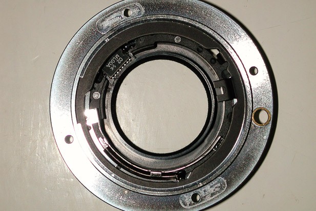
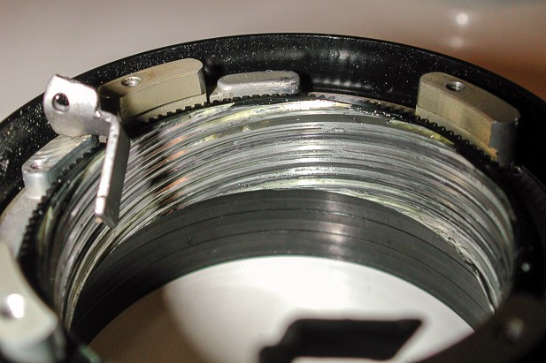
The autofocus coupler can be seen at about six o’clock, it interfaces with the outside of a “barrel” that runs the length of the lens case (the outside portion that you hold on to). This “barrel” is threaded on the inside. The plastic case that holds the glass and aperture (the lens) is also threaded, so that when the outside “barrel” turns, the lens moves downward (in the orientation of this picture) and that is how focus works.
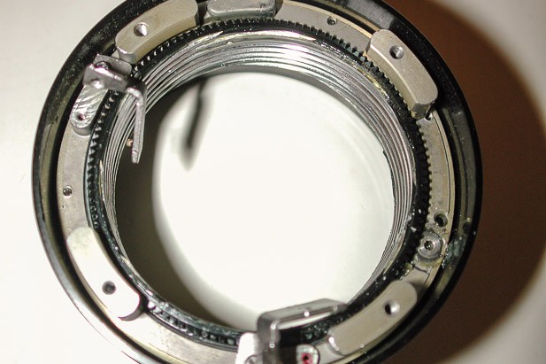
The next task will be to remove the two braces at the twelve o’clock and eight o’clock positions. They seem to be the only things keeping the lens from falling out of the front of the case when you focus it. They jut out a few millimeters from the side of the lens case, and are bent 90 degrees downward and go into the plastic that hold the glass. I assume they are screwed onto a plate on the plastic that is able to move up to the minimum focusing distance.
Well, I ran into a problem with removing the screws from the braces. I was able to get one screw off of each brace, but the second screw on both got stripped. They are both very small screws and I tried everything short of epoxing a screwdriver to it. I used a pair of pliers and attempted to pry it up so that either the screw would break, would pull out of the housing, or break the brace near where the screw was holding it in.
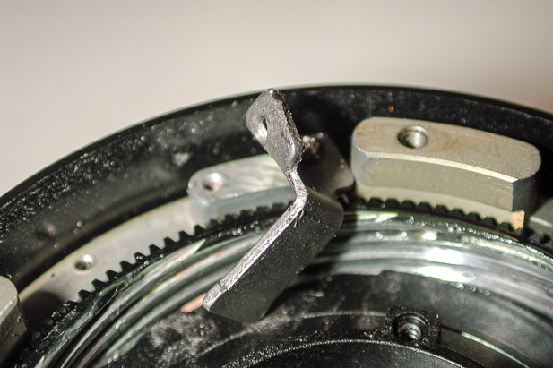
As it turned out, the brace wasn’t screwed to anything at it’s other end. As you can see in the picture, it is flared on the sides, and the flared pieces fit in a little track that is on the side of the plastic that holds the glass. When I bent them, they came right out of the track and the lens was able to fall freely out of the front of the lens case.
The aperture “staff” is sticking up from the upper right portion of the lens.
The front and middle groups were a different story…
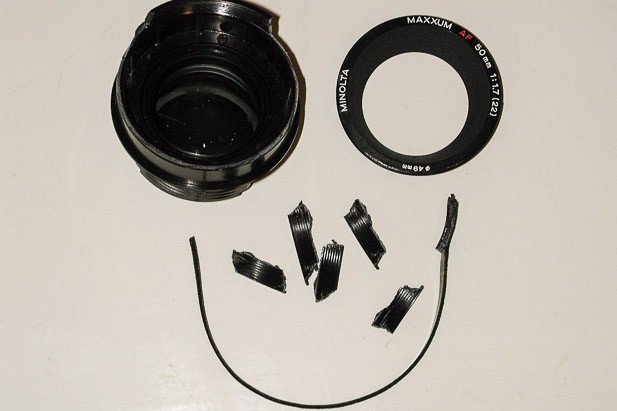
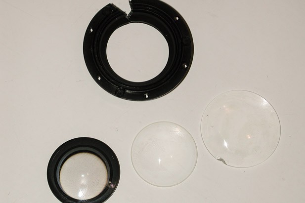
It looked like the front elements were being held in place by the plastic collar in the front of the lens (in the upper right corner in this picture). Unfortunately, to remove it, I had to break off a plastic lip at the very front of the lens (seen in pieces in the middle of the picture). On the inside of this plastic lip was a felt band (seen in the lower portion). I had to remove about ¾ of the lip before the collar came free.
All that remains is the aperture mechanism, which seemed to be below a piece of plastic. This piece of plastic was held in place by a metal wire running around a channel where the plastic cover meets the walls of the lens. At the ten o’clock and one o’clock position there’s some green “goop” that is holding the metal in place.
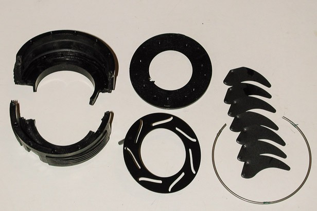
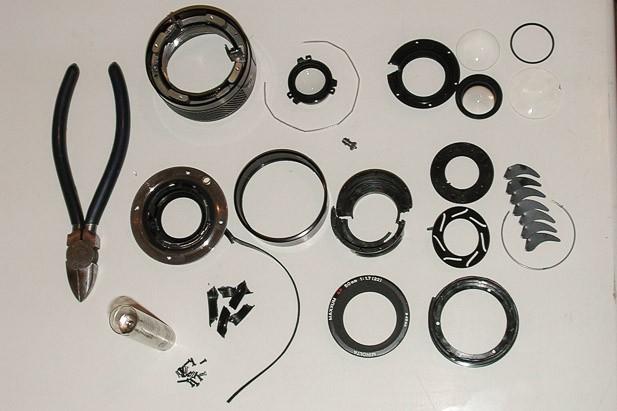
I could not remove the metal out of the channel, so I had to break the plastic outer case (two pieces on far left) that the aperture was held in. The blades were held in the notched plastic (center, bottom) with the cover on top (center, top). As the notched plastic moves, the blades close or open.
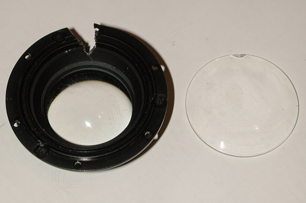
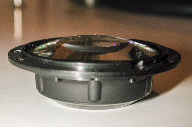
The front element was held in place by a plastic collar. Unfortunately, when I broke the collar, I also chipped the glass (twelve o’clock).